


LP1425 11x14”
Semmendinger Field View Camera
- Rehabilitation and Rear Platform Reproduction -
____________________________________________
LP1425 is a large wet-plate Semmendinger Excelsior Variation 1 view camera purchased on eBay on 11 Nov 2023. It was apparent from the eBay photos that it was a folding field camera, but that it was missing the rear platform that was probably hinged at one time to the main platform.
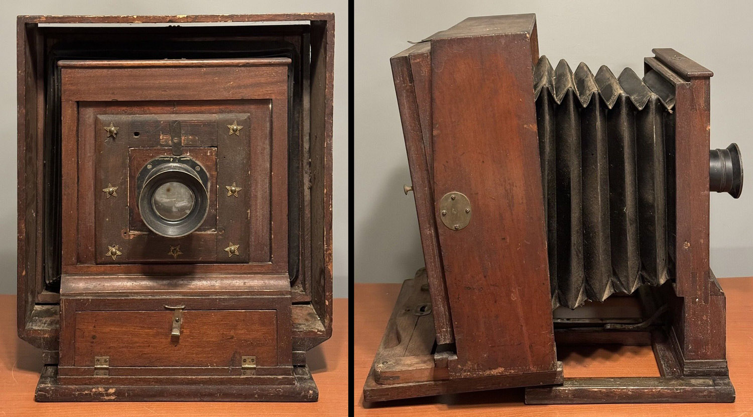
Photo 1: eBay photos of camera as received. The damage to the rear of the main platform is not visible in any, but the lack of a rear platform is evident.
Since I have made approximately a half dozen camera backs/ground glass frames utilizing the type of wood joint (bridle joint) that the rear platform would have, I decided to buy it, and reproduce its rear platform to the best of my ability.
Upon receipt, I found that the rear platform was, indeed, missing, but,
in a minor miracle, the two large bolts that are used to make the rear
and main platforms rigid were contained in the little compartment at the
lower part of the front standard.
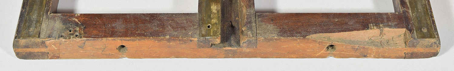
I also found out why the rear platform is missing – in some kind
of dropping incident, the rear platform pulled out both hinges from the
main platform, as well as a significant amount of wood at the right
hinge, and a large part of the right side of the t-shaped channel used
for the brass combined fine-focus screw/focus lock device, which is also
missing. In addition, one of
the brass tracks on which the rear standard rides was quite bent, being
screwed to a part of the camera which is now missing.
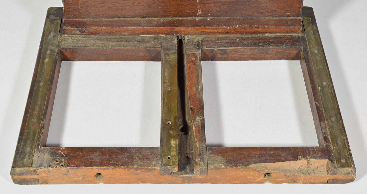
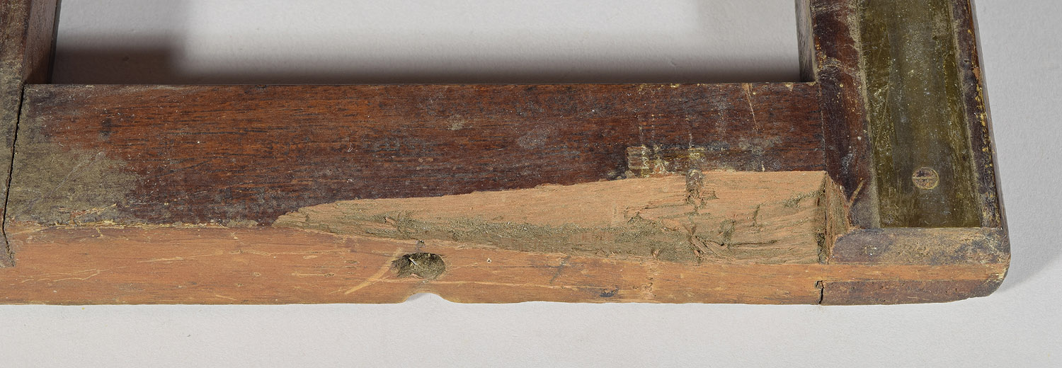
Photo 3:
Close-up of the right rear side of the main platform.
The missing wood extends almost half-way through the rear
cross-member.
The wood comprising the main platform is 15/16” thick and 1 3/16” wide. Paul Semmendinger, who keeps track of extant Semmendinger cameras (current count, 33) was able to take photos and take measurements of another 11x14” folding field camera, where we found out that the rear frame to be reproduced is 19” long by 15” wide. The sides and ends of the frame are 1 3/16” wide, and there is a 2” wide piece running down the center that has a t-shaped slot for the fine focus device.
1. Wood
Mahogany is a
collective term referring to about 30 different species of reddish
hardwood. The species used in the 1800’s for camera manufacture is
no longer readily available. The closest mahogany to antique
camera wood is called genuine mahogany in the hardwoods store I
frequent. I think this same wood was called Honduras mahogany at
one time. So this was the wood I chose with which to make the rear
platform.
The thickness of hardwood called 1” nominal thickness
is actually 13/16”. This is 1/8” too thin. I therefore had to buy
a 2” nominal thickness board (actually 1 3/4”) and have it planed down
to 1” thickness. I planned on having the frame sanded in a 3’ wide
sander that they have at the hardwood store, so I didn’t have it planned
to exactly 15/16”. I will also make the dimensions of the frame
1/4” larger than the original (1/8” per edge), so that it can be trimmed
to exact measurements after it is glued together.
The woodworking tools used will be a circular saw for
rough cutting, a table saw for fine cutting, a jig for holding wood
straight up while being cut in the table saw, a router for the t-slot,
and a set of 4 clamps having right angles to glue the frame precisely.
2. Center Rail with T-Slot
I thought that the center rail, with its T-shaped slot for the fine focus screw would be the trickiest to reproduce, so I started with this first. I had never done something like this, whereas the rest of the rear platform would be four pieces of wood connected with bridle joints, the same type of joint that I had used to make a number of missing ground glass frames/backs. It’s not exactly a “T”, but rather an upside-down “T”.
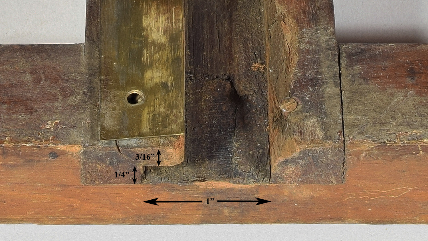
Photo 4:
Close-up of the end of the original center rail of the main
platform
It turns out that router bits that cut a T-shaped slot do exist, but not
in the size necessary to match the one in the main platform, which has a
vertical part 1/2” wide, and a horizontal part (the top of the T) 1”
wide and 1/4” high. Thinking
of them as separate was the key to doing it.
A 1/2” diameter straight router bit does the vertical of the “T”,
and there is a router bit that will do a 1” x 1/4” hole, once the 1/2”
vertical has already been cut.
The router has a 6” diameter round platen, the bit being held in the
middle, 3” from the edge. So
I could set up a fence using a straight board, which the router platen
could slide down. The center
rail is 2” wide, so the fence has to be 4” from one edge of the center
rail. Obviously, the slot
had to be cut before the center rail was cut to final size.
I used a large piece of maple plywood that I had used to make
shelves (to hold cameras, of course) for a flat substrate unlikely to
cause the router to wiggle or pause.
To this was clamped a full width (6”) piece of my 1’ thick
mahogany, and a 1x2” piece of pine that had a straight edge as the
fence. The fence was
positioned 4” from the trimmed, straight edge of the mahogany.
It was really easy to keep the two cuts centered with each other – don’t
move the fence. I realized
that I could merely make one cut after the other (adjusting for proper
depth when changing bits) and it was done.
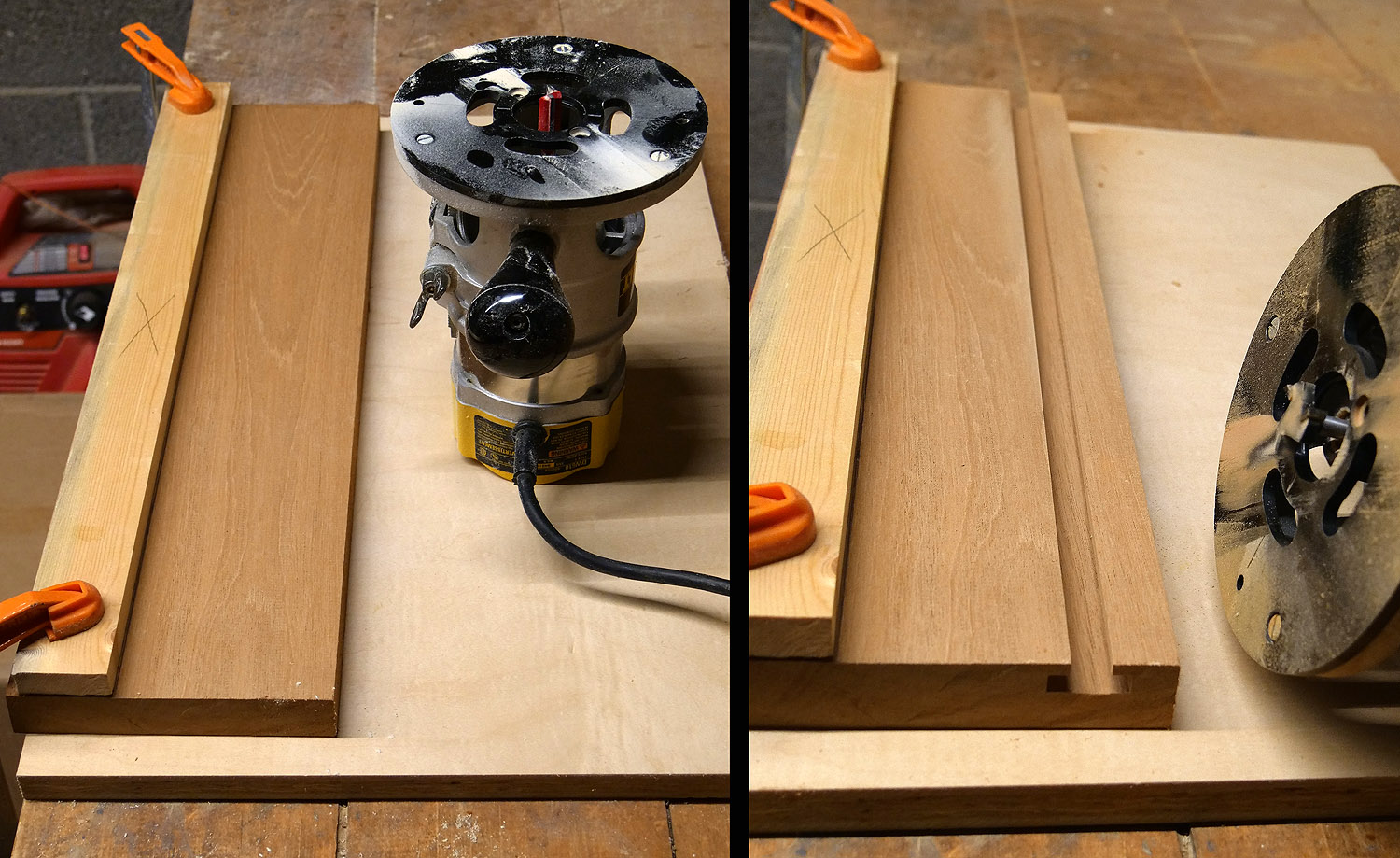
Photo 5:
The cutting of the “T”-slot for the new rear platform.
Left: before cuts.
Right: after both cuts.
All that was necessary to finish the center rail was to rip the piece to
2” wide.
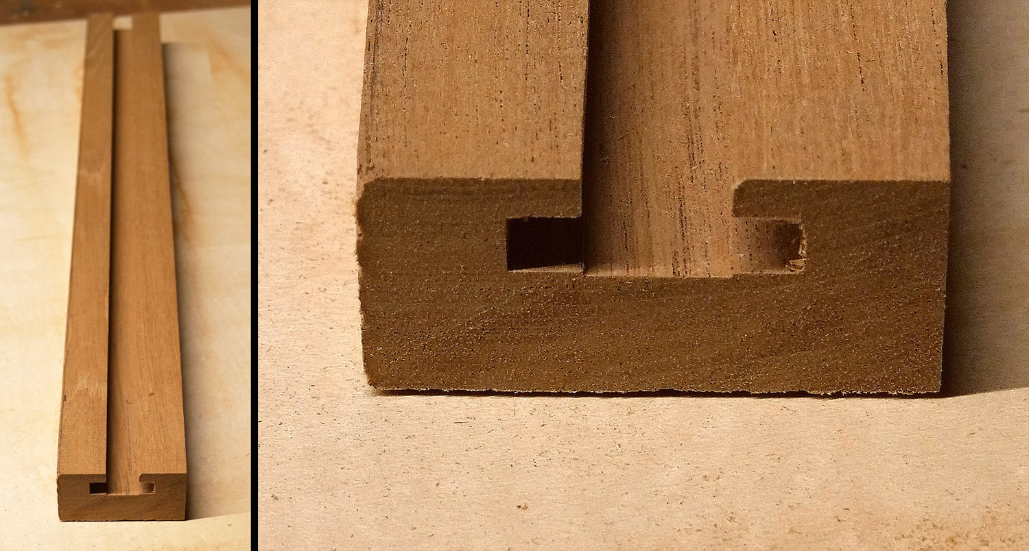
Photo 6:
The center rail to size.
Left: full shot.
Right: close-up of one end.
3. Side Rails
The side rails are to be 19 1/8” long, 1/8” longer than the final
length, leaving 1/8” to be allowed for some slight trim on all sides
that will even up some misfit of the joints.
The joints at the corners are bridle joints, which require a slot to be
made in the side rails and two rabbets on the end rails that will create
a block at each end to fit into the slots.
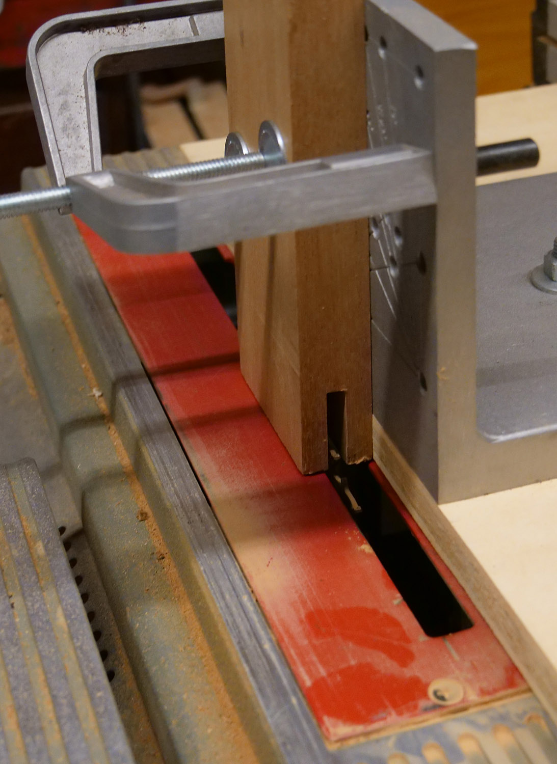
Photo 7: Cutting a slot in
the side rails. The rails
are still one piece for now.
This is the first cut, made with a normal saw blade.
The piece will be removed and turned around for the second cut in
order to make a perfectly centered slot.
A centered slot will allow all the rabbets to be cut to the same
depth. The depth is 1 1/4” (1/16” greater than the projected final
depth).
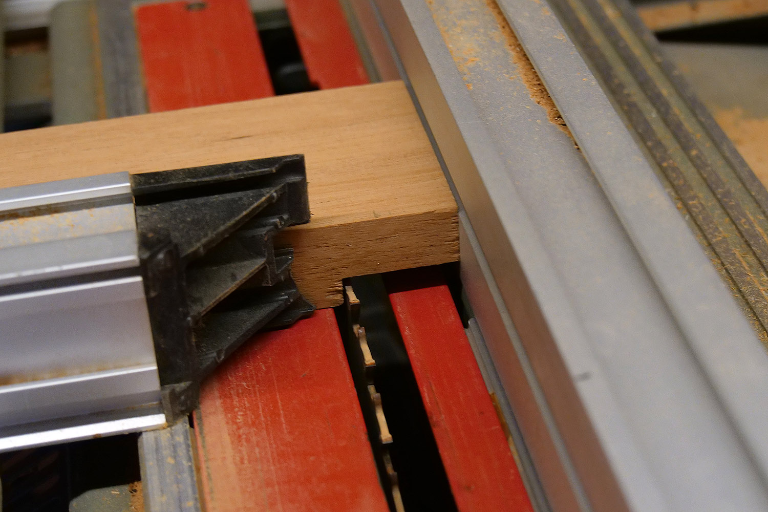
Photo 8: Cutting the first
rabbet on the end rails (which haven’t been ripped to width yet to make
the rabbets exactly the same for each rail.
Both rabbets on this end will be cut, then test fitted to the
already cut slots in the side rails, the cut a little deeper until the
end fits in the slot.
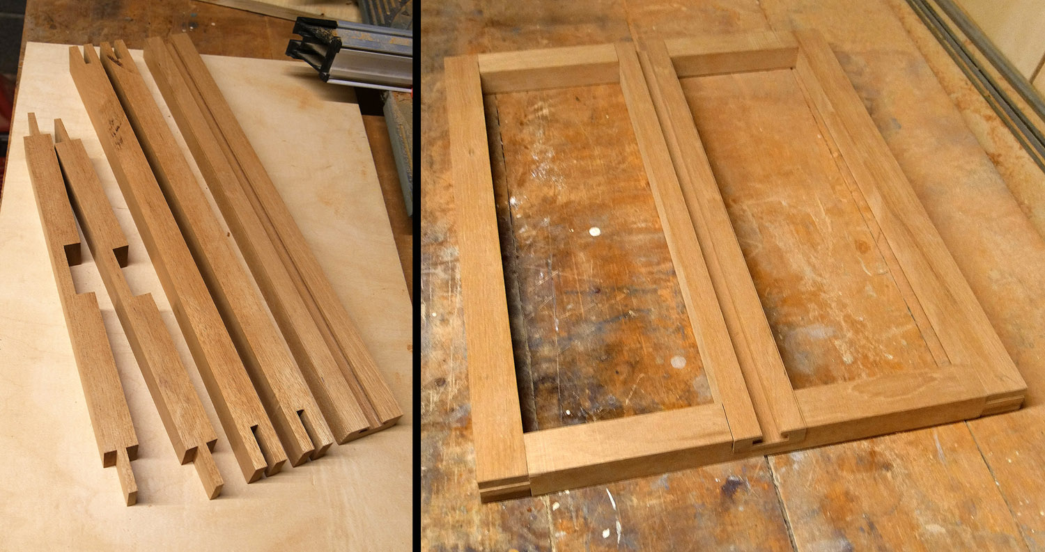
Photo 9 (left):
The finished two ends (left), two sides (middle), and center rail
(right).
Photo 10 (right):
A dry-fit of the parts.
4. Assembly
To glue the ends and sides together, a commercial corner-jig setup is
used, consisting of four square corners, each of which is clamped to an
end and a side.
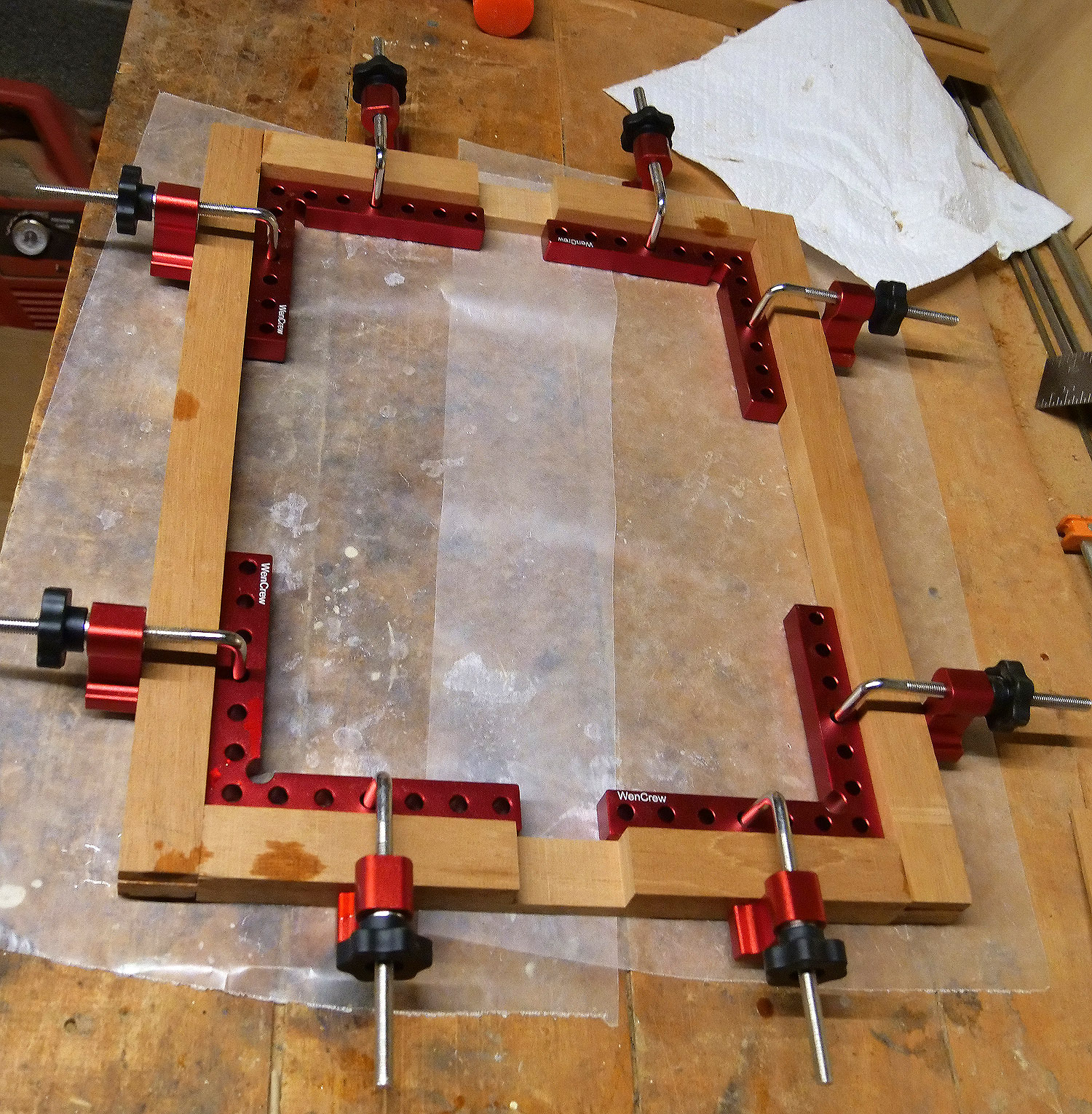
Photo 11:
Gluing the ends and sides.
Then the center rail is glued.
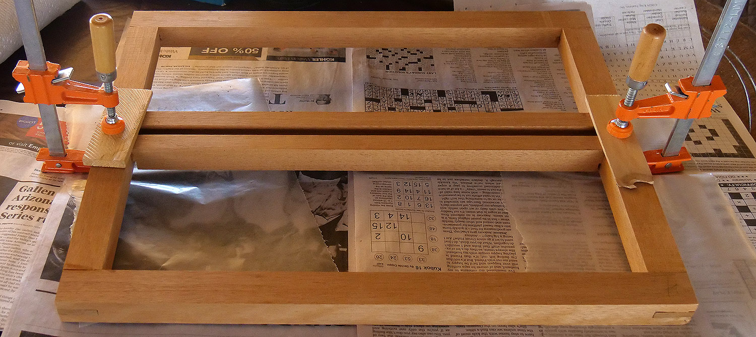
Photo 12:
Gluing the center rail.
Since the stock was 1” thick and the original camera rails are 15/16”
thick, the assembly was taken to a woodworker’s shop that had a large
sanding belt. The front was
minimally sanded (we don’t want to make the t-slot any shallower than it
already is), and the back sanded until the thickness was 15/16”.
The original sides are slightly rounded, which presents a problem.
The closest solution was to use a
1 1/2” Convex Edge Oval Router Bit
(the largest available, since they are usually used for stair treads).
To use a 1 1/2” tall bit on a 15/16” thick edge, the frame had to
be clamped on a pedestal (to make the middle of the over-large bit
coincide with the middle of the frame edge), then a large flat and
smooth piece of wood was clamped on top of the pedestal for the router
plate to slide on. Finally,
a wooden fence was clamped on of the smooth piece to keep the router
parallel to the edge. The
distance from the fence to the edge of the frame was determined by trial
and error – starting too close and gradually attempting to remove wood
at the top and bottom of the frame but not in the middle.
It turned out that I misread the amount of wood removed, and
ended up taking off about 1/16” on each side of the frame.
It is now slightly less wide than the original.
For about 1 second, I considered starting over and making a
second frame, but it was about two weeks work - so, no.
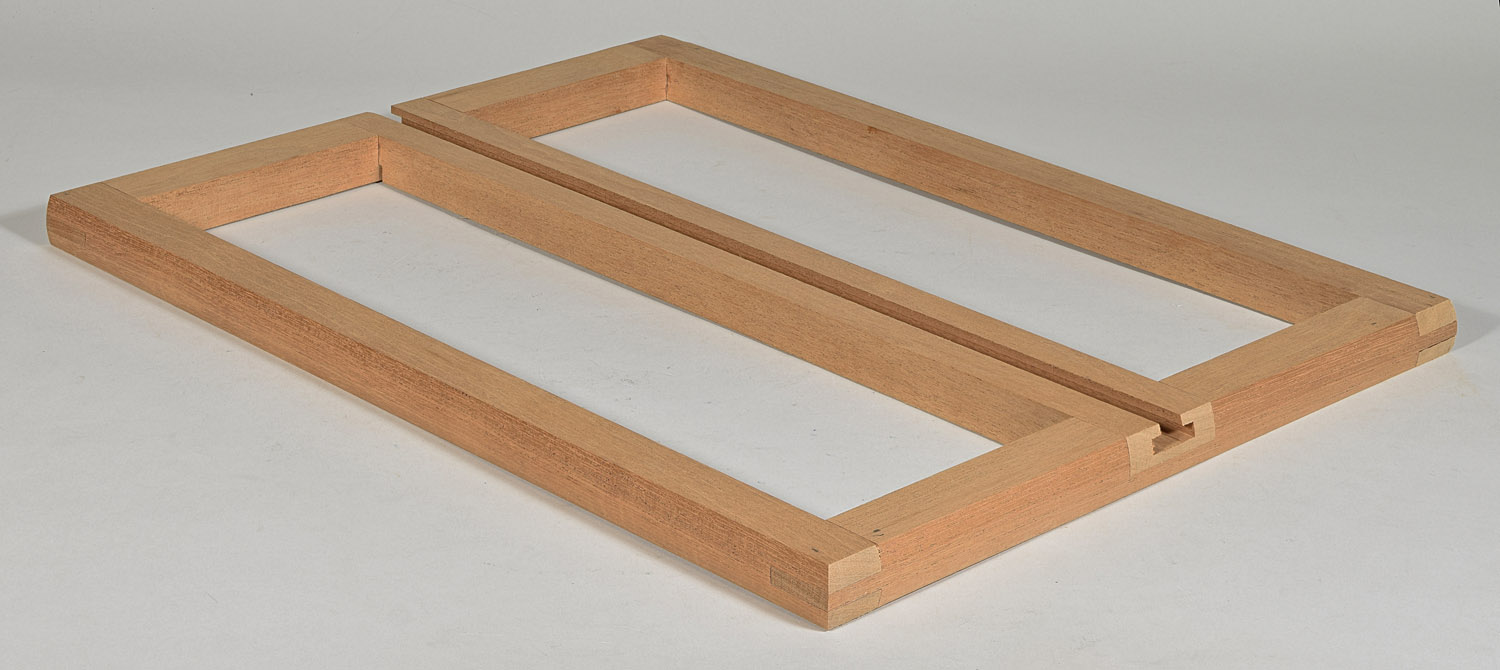
Photo 13:
After Sanding and Edge Rounding.
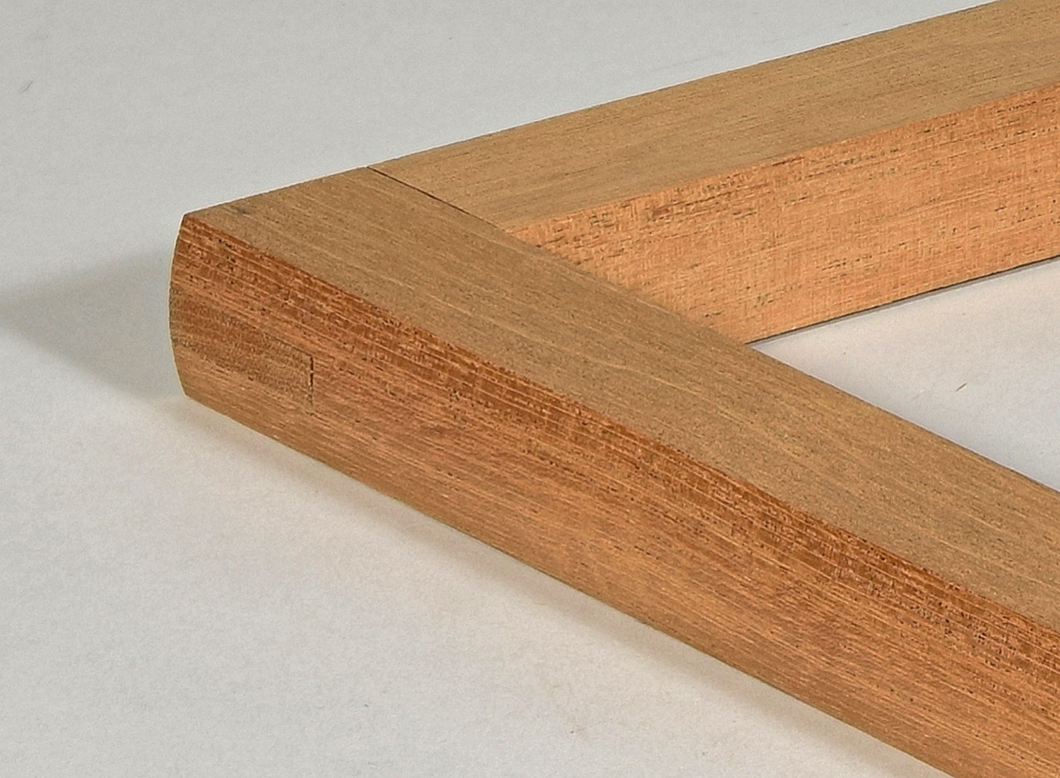
Photo 14:
Close-up of Edge Rounding.
The photos above show sharply cut edges, whereas the camera has
eased,
i.e., slightly rounded edges.
This was done during final hand sanding with 100, 150, 220 and
320 grit sandpaper.
5. Wood Finishing
It appeared that the camera color was very near a red mahogany gel stain
that I had, but the platform was much darker along the edges, and rather
light on vertical surfaces.
This was only noticed after some staining had already taken place, so is
only of use as a post-mortem.
To obtain an even stain, the wood must first be sealed with a thin coat
of spray shellac. This
prevents the stain from soaking in unevenly.
Mahogany is not as uneven as other woods, such as cherry and
pine, so it may not have been necessary, but with the amount of work
going into the platform, it couldn’t hurt.
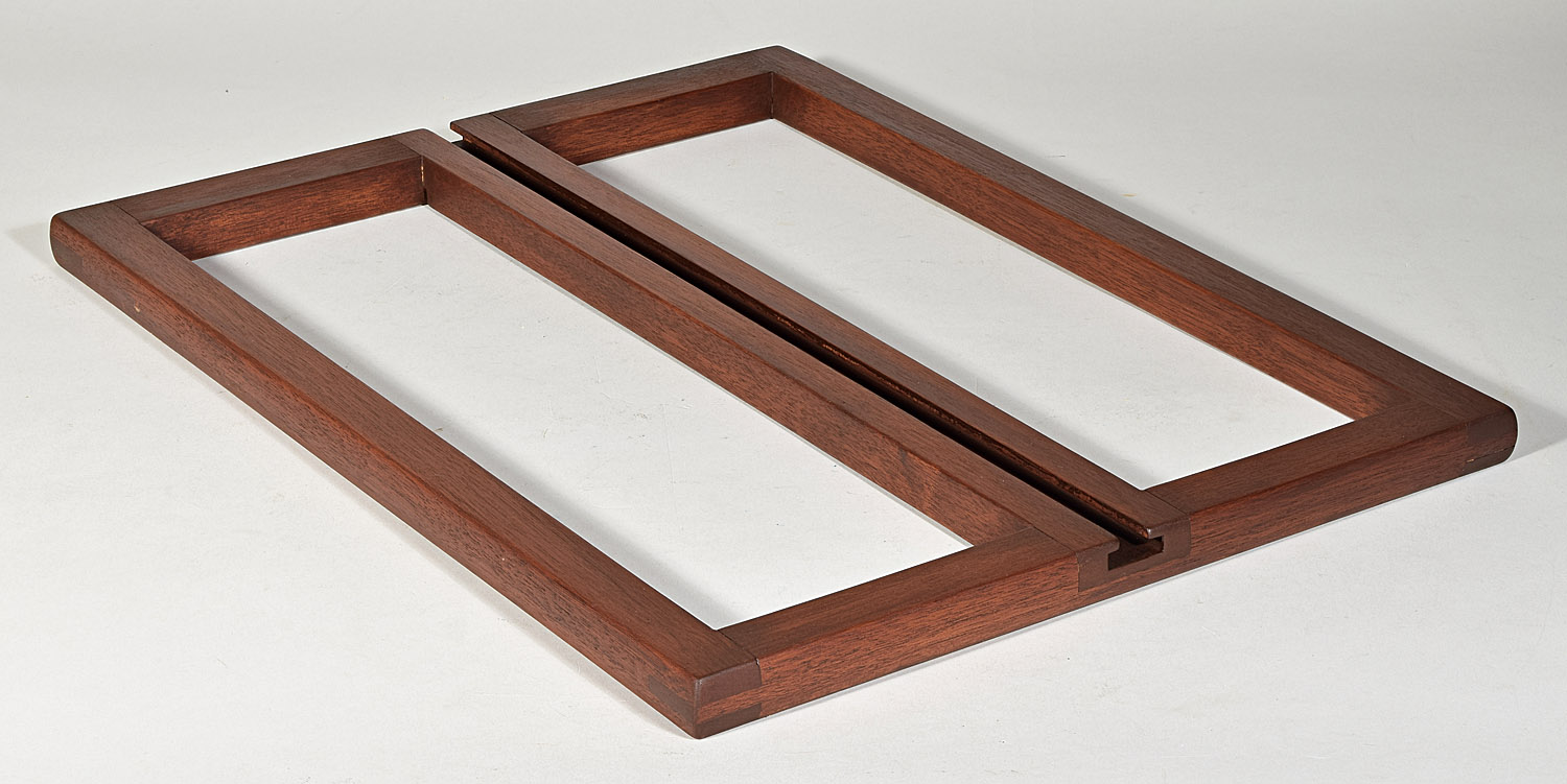
Photo 15:
Red mahogany gel stain base coat.
Then, when it was a good match for the camera
body, but too light and red for the camera platform, a coat of American
Walnut was added. I should
have only put it on the top and sides, leaving the vertical surfaces
lighter, but too late now.
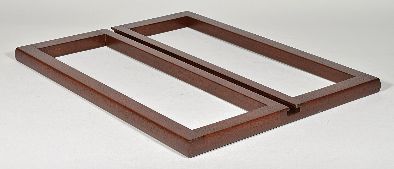
Photo 16:
American walnut over red mahogany gel stains.
This is much closer to the color of the top and sides of the original
platform, but the stain is too uniform to suit me.
The work involved in stripping it and re-staining, though,
convinces me to not mess with it any more.
From the distance in a usual museum display, the reproduced part
is convincing enough.
As usual, I stamped my initials and date – LP 2024 – into the bottom of
the reproduced part so that there is no doubt that this is a reproduced
part. I rubbed black paint
into it so that it is visible but subtle.
6. Making the Rear Platform
Functional
The original rear platform was ripped off the main platform leaving two
stripped screw holes from which the hinge was pulled out on the left
side, and leaving a missing piece of the main platform on the right
side. There is also a piece
of wood missing from the right side of the center t-slot, which would
prevent the rear standard from being locked when the camera is folded –
that is, if I can ever obtain a fine focus mechanism that fits.
Photo
17: Damage at the rear of
the main platform.
The screw holes on the left side were filled in using my personal
formula wood filler, consisting of mahogany saw dust mixed with enough
hide glue to make a paste.
The hide glue is soluble in hot water, so the fix is technically
reversible, although I certainly wouldn’t want to try to get them out of
those holes.
The missing piece on the right is not just a cosmetic problem.
The missing piece contained the right hand hinge for the rear
platform – a necessary part for the rear platform to be functional.
The missing chip extends into the platform about 3/8”, stopping
right where the middle slot and rabbet start in the bridal joint.
The right edge of the missing piece runs along the left edge of
the side rail. If I tried to
make a piece to fit only in the missing hole, there is no way that it
could have a strong enough bond to the remaining wood to support a
hinge. So I decided to cut a
dado 1/3” deep extending from the right rail for 2 1/4”.
That would allow me to install a rectangular patch that would be
able to be strongly glued, even using hide glue.
The dado will be made as I usually make them – a series of circular saw
kerfs that span the required distance.
I this case, I cannot use the table saw because the front
standard will not come off of the main platform.
The three large screws that usually secure the front standard
came out easily, but someone must have glued the standard bottom rather
well, because I could not crack it loose, even using a chisel and hammer
(carefully). Therefore this
dado would be cut using a 4” diameter battery powered circular saw.
To keep the saw within the 2 1/4” boundary and to keep the saw
from cutting too deep, a board was clamped over the area to be cut, and
the boundaries drawn on the board.
Notice that the dado has been purposely left short of the hole in
the end of the platform that accepts one of the 5/16” thumbscrews that
make the two platforms rigid.
I certainly didn’t want to try to duplicate the inlet brass piece
that is present on the far side of the hole.
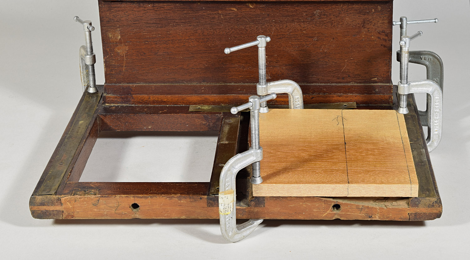
Photo 18:
Set-up for dado for hinge patch.
The cuts did not turn out as slick as anticipated.
As the top board gradually got cut away, instability in the saw
caused some cuts to slightly lower than planned.
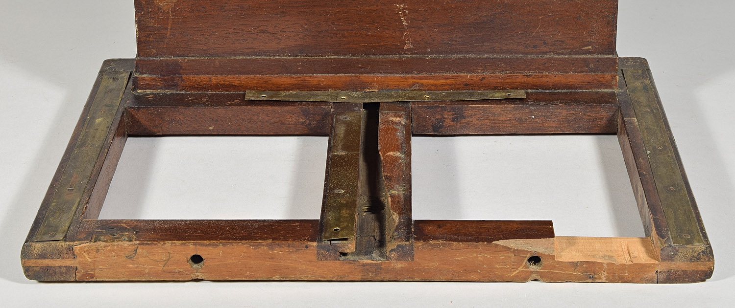
Photo 19:
Completed dado for hinge patch.
Not enough to prevent a good bond with the hinge
patch, however.
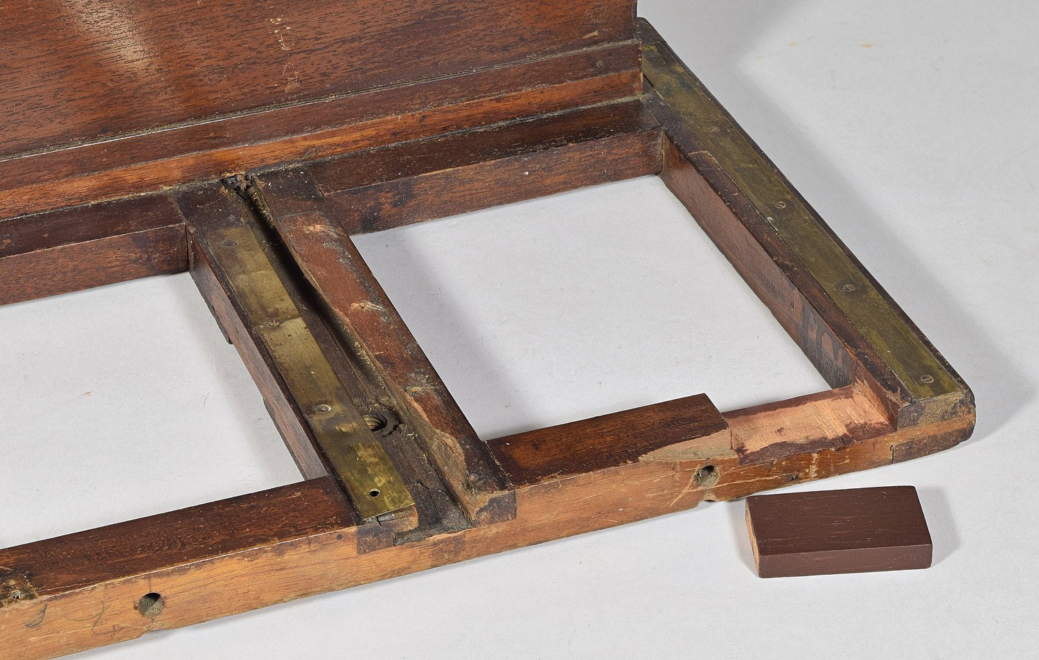
Photo 20:
Hinge patch before being glued into the patch dado.
The hinge patch was glued with hide glue, as
usual. The small crack
caused by saw blade drop was stuffed with my mahogany sawdust/hide glue
wood dough.
5. Final Touches
The rear platform was originally attached to the main platform by six
screw hinges (three on each side).
I would have used replacement hinges of the same size if I could
have only found some. I
therefore turned to my collection of antique camera pieces and parts,
and found two matching 6 screw hinges having a nice patina similar to
the original brass parts on the camera, that are slightly larger and
probably stronger that the originals.
To find the exact spots to drill holes in the rear platform to match the
locations of the originals in the main platform, I used a very sharp
drill, pushed from the inside of the original holes to mark the center
of holes to drill in the rear platform.
Using a drill 1/64” larger than the 5/16” thumbscrews that will
go through them, I drilled holes, attempting to keep the drill at right
angles to the rear platform.
Below is a photo of the rear platform with hinges and thumbscrews
providing a rigid connection to the main platform.
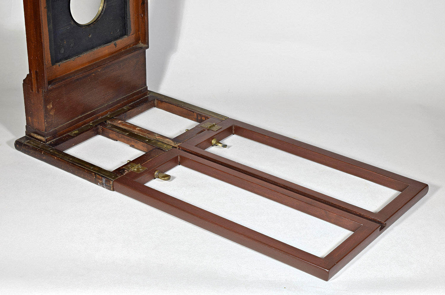
Photo 21:
Hinges and thumbscrews finished.
Another small detail remaining is the missing wood in the center rail of
the main platform.
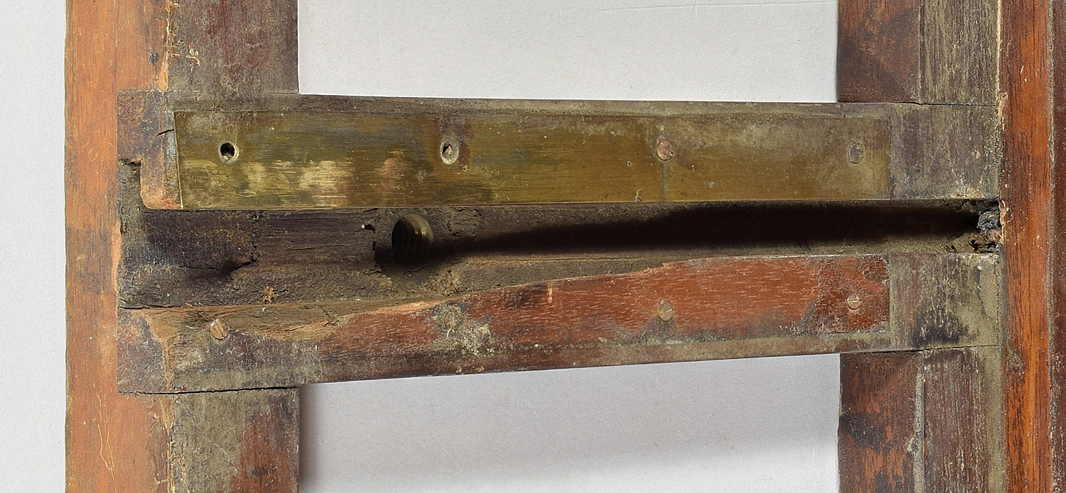
Photo 22:
Missing wood in center rail of main platform.
I decided to patch this, since the rear standard could not be fixed for
transport without this vital missing piece.
Also, the brass strip that is to be re-installed over the missing
piece cannot be firmly attached without it.
The metal strip had been bent back on itself due to the
instability caused by the missing wood.
The other brass strip was held only by one screw and a nail, the
bottom two screws being missing.
A paper pattern of the missing wood was made by pressing Xerox paper
against the break to create a crease, then cutting along the crease.
The pattern was then transferred to a practice center rail in
which I had previously routered the t-slot.
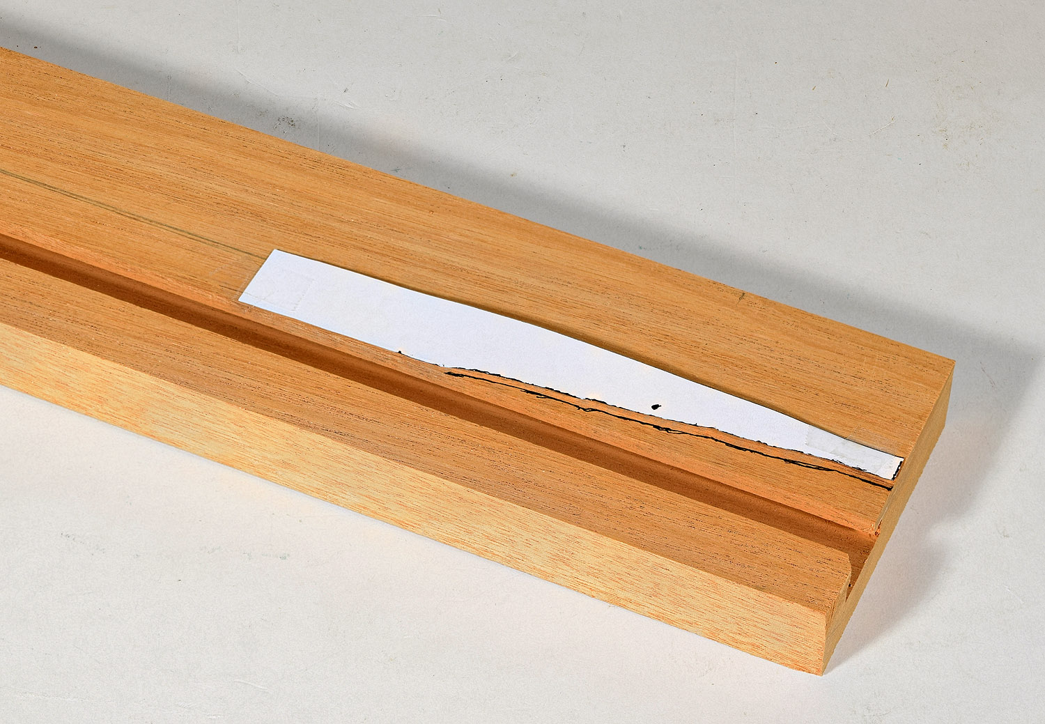
Photo 23:
Transferring the pattern of break to a practice center rail.
A 1/4” chisel was used to create a scored line
matching the line of the break, but slightly larger.
Further chiseling caused the piece to break approximately like
the original camera piece broke.
The piece was then laboriously carved with wood carving tools
into a condition where it fit more or less into the missing area.
The piece was then glued and clamped into position.
Any remaining cracks were filled with the type of wood dough
discussed above.
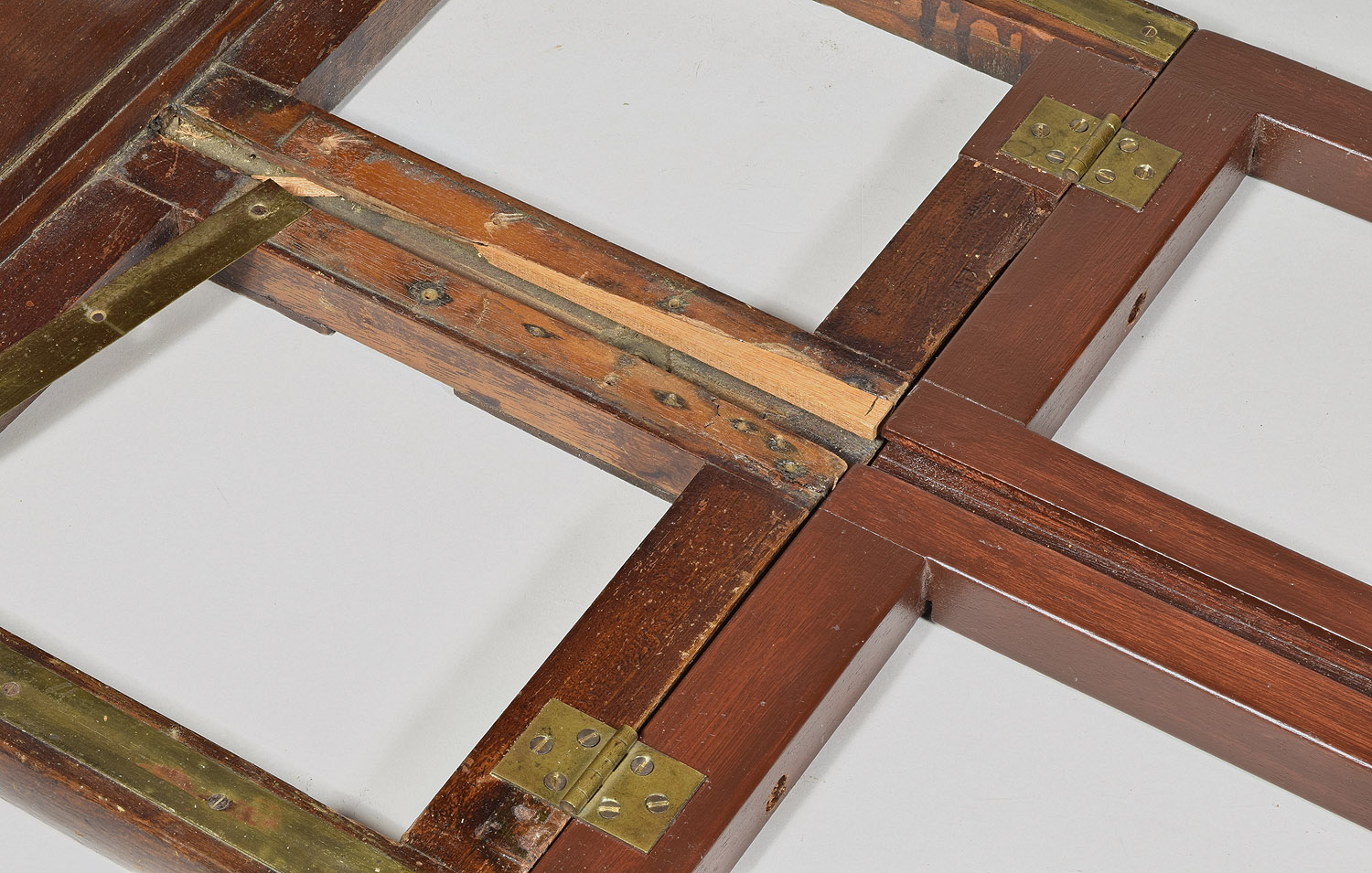
Photo 24:
The patch installed.
The patch was then painted, using a 1/4” brush, with stains to match the
surrounding wood.
The screws originally used to fasten the brass strips along the center
rail (and probably all the screws in brass strips wherever they are)
were No. 3 and 1/4” long, which only have a few threads.
The screw holes were no doubt stripped when the accident
happened. The screws were
located above full thickness wood, so there is no reason to keep using
1/4” screws. So the screws
of both strips on the center rail were replaced with 1/2” No. 3 screws
after pre-drilling the holes for the greater depth.
The exceptions were 1) one location in the left hand strip, which
had been nailed after the accident, and the nail could not be removed
without damaging the strip, and 2) the location over the largest part of
the new patch in the right side of the center rail.
The crack in the rail had run directly through this screw
location, so any attempt to screw into that location would be liable to
start a crack between the patch and the rail.
In this case, a No. 3 screw 3/4” length was used.
The pre-drilling included a normal diameter hole 3/4” deep but
also a greater diameter hole 1/4” deep, to prevent the screw from
pushing the patch away from the rail. The
pre-drilling succeeded, as can be shown in the photo below.
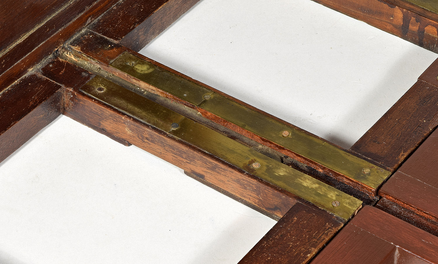
Photo 25:
Original brass strips re-installed over the patch.
6. Refinish of the Rear
Platform
The original main platform is much darker than the upper parts of the
camera. It may not even be
the same type of wood, as, although the grain in the fracture looked
like mahogany, the color of the platform is not as reddish as the more
obviously mahogany parts.
In trying to make the reproduction mahogany rear platform as dark as the
main platform, I used gel stain, which can be put on thicker than
old-style thin pigmented stains.
But by the time the part looked dark enough, the finish was thick
enough to look obscure the grain of the wood, and it looked more like
paint than stain. I
therefore took off the rear platform and removed the vast majority of
the it’s finish using a finish
restorer, a solvent capable of dissolving all kinds of finish,
gradually thinning the color.
I left some of the color on in areas, making it uneven, kind of
like the original main platform, which has been left uneven by rough
handling and wear. I sanded
the bottom and inside end of the platform, areas that hadn’t been
stained or finished on the original platform (I had failed to take these
differences in account when finishing it the first time.
The new darkening agent was an aniline dye, which dissolves in alcohol
to make a concentrated stain, and comes in as wide a variety of colors
as any other type of stain. Given the non-red color of the main
platform, dark walnut dye was used.
Dye has the advantage of not being a pigment, and can be made
darker without obscuring the wood grain, as happened during the first
wood finish.
The first application of dye and alcohol was not quite dark enough.
Putting another application on seemed to move the first dye
around somewhat, so it was decided to add dye to a solution of shellac
(conveniently also dissolved in alcohol).
I used a garnetlac preparation that I previously have used on
lots of lens board reproductions.
Garnetlac is the darkest of shellac types and is probably similar
to the shellac actually used in the 1800’s.
Using this garnetlac-dye for the second application resulted in a
color and darkness very near that of the original platform.
A final thin application of walnut gel stain to the sides of the
reproduction platform brought it as near to matching the main platform
as feasible.
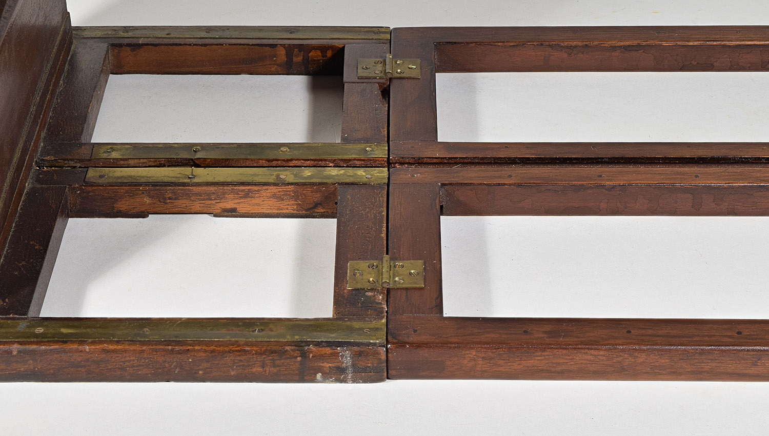
Photo 26:
New rear platform (right) installed with period hinges to the
original main platform (left).
One thing that was evident when comparing the reproduction to the
original platform is that the underside should not have any stain or
finish at all – the original is just aged wood.
Therefore, in addition to removing my aborted first try at wood
finish, the underside was sanded to remove most of the stain, although
there are grain streaks that would require so much sanding as to change
the dimensions of the wood.
So the streaks were left. A
single application of walnut dye and alcohol was made to darken the wood
without the use of shellac or varnish.
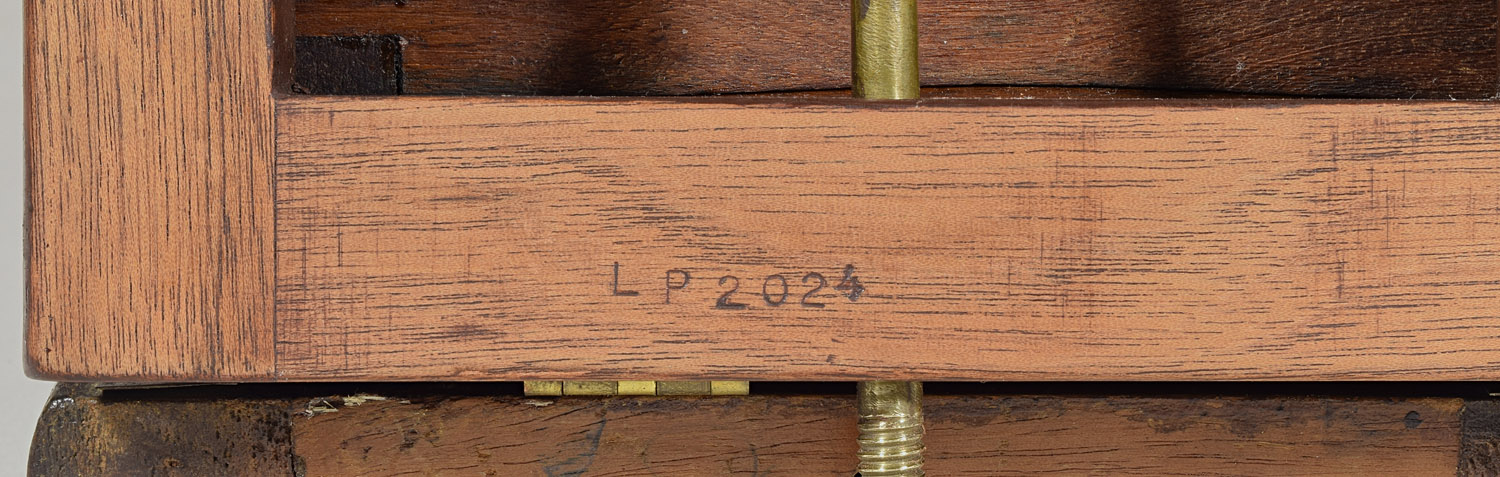
Photo 27:
Bottom surface of replacement platform, with stamp indicating
year it was made.
Over time it might age to better match the original.
The bottom is stamped with my initials and the year, a procedure
that I have followed for all of my reproductions of camera parts, even
though it is not likely that anyone would mistake them for original
parts.
7. Little Metal Strips
The original main platform has thin metal strips on which the rear
standard rolls. A
measurement showed that the metal (brass) had a thickness of 30 gauge
(0.01 inch. Unfortunately,
the thinnest gauge brass that I could obtain was 26 gauge (0.015 inch).
I think the thicker metal is a plus, in that it has more metal to
which the wood screws can hold, making it less likely that the strips
will pull out over the screw heads, as happened to the main platform at
some point.
It is not obvious upon first look, but the original strips have two
widths – one width for strips on the center rail and a width for strips
on the side rails that is about 1/16” less.
Fortunately, I took the main platform with me to the metal
supplier, where we could measure the widths and adjust the cutting
machine accordingly. Oddly,
the width set on the giant machine wasn’t what the width of the strip
coming out would be. We had
to cut by trial and error to get the widths desired.
The strips were left with slight burrs along each cut, a problem easily
removed using a steel file.
Each strip had to be fastened to the wooden rails by flat head, slotted,
brass wood screws. The
screws on the original part were separated by a little over 2 inches.
For our 19” long platform, a separation of 2 3/16” was used,
measured on the first, which was then used as a template to mark the
positions to be drilled for the others.
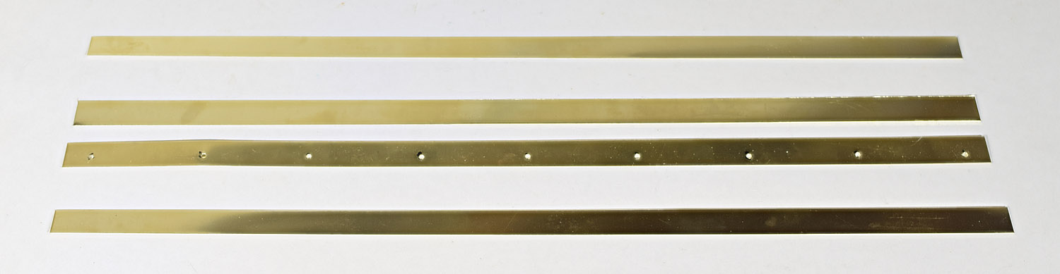
Photo 28:
The four brass strips for the rails.
One has had holes drilled.
The screws used for the original platform were No. 2 of varying lengths.
I used 3/8” long No. 2 for the new platform.
To simulate tarnish from age, the screws were first de-oiled by
soaking in denatured ethanol, then tarnished using a few drops of
Birchwood-Casey Brass Black.
The dilution of the brass black makes the reaction slow enough that one
can remove the screws at the desired darkness of tarnish.
The screw holes must be counter-sunk in order that the screws not stick
up and impede the movement of the rear standard.
After counter-sinking, the strips
were each tarnished using the same solution as for the screws, except
that the liquid had to be brushed on.
The result was not exactly uniform, but then the tarnish on the
original strips is not uniform either.
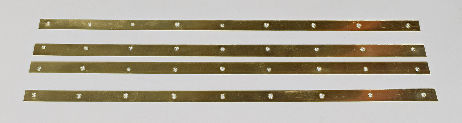
Photo 29:
The four brass strips, drilled, counter-sunk and tarnished.
The counter-sink bit did not cut cleanly.
When the brass got thin enough, it deformed into the shape of the
bit rather than being cut.
That the shape extended below the strip pointed out to me that
counter-sinking the brass alone would not be enough to provide room for
the heads of the wood screws.
So after marking and pre-drilling the screw holes, the wood was
also counter-sunk.
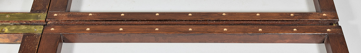
Photo 30:
The screw holes have been pre-drilled and counter-sunk.
The brass strips were then installed using the 3/8” long screws, without
the stripping of threads which may have happened without
pre-drilling and counter-sinking.
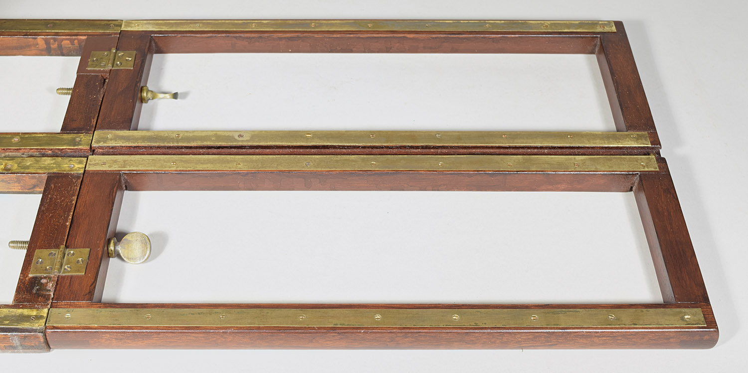
Photo 31:
Brass strips installed.
In tightening the screws, I even continued a practice seen in high-end
camera models: aligning the screw slots parallel to one another.
I had read that this was done by trial and error, eventually
finding screws that, by chance, tightened up to be parallel.
In this case, the screws felt like they could have been tight
enough over an angle greater than 180⁰.
That is, I never had to exchange screws to get them aligned.
Before reassembling the camera, it required cleaning, having probably
been stored in a basement, attic or garage for decades.
It was the dirtiest camera I have ever seen. It was cleaned with
damp paper towels, requiring as many as 10 such towels to clean a small
(10 sq. in.) area.
Below is a rear view of the finished camera, the rear standard supported
on its new rear platform.
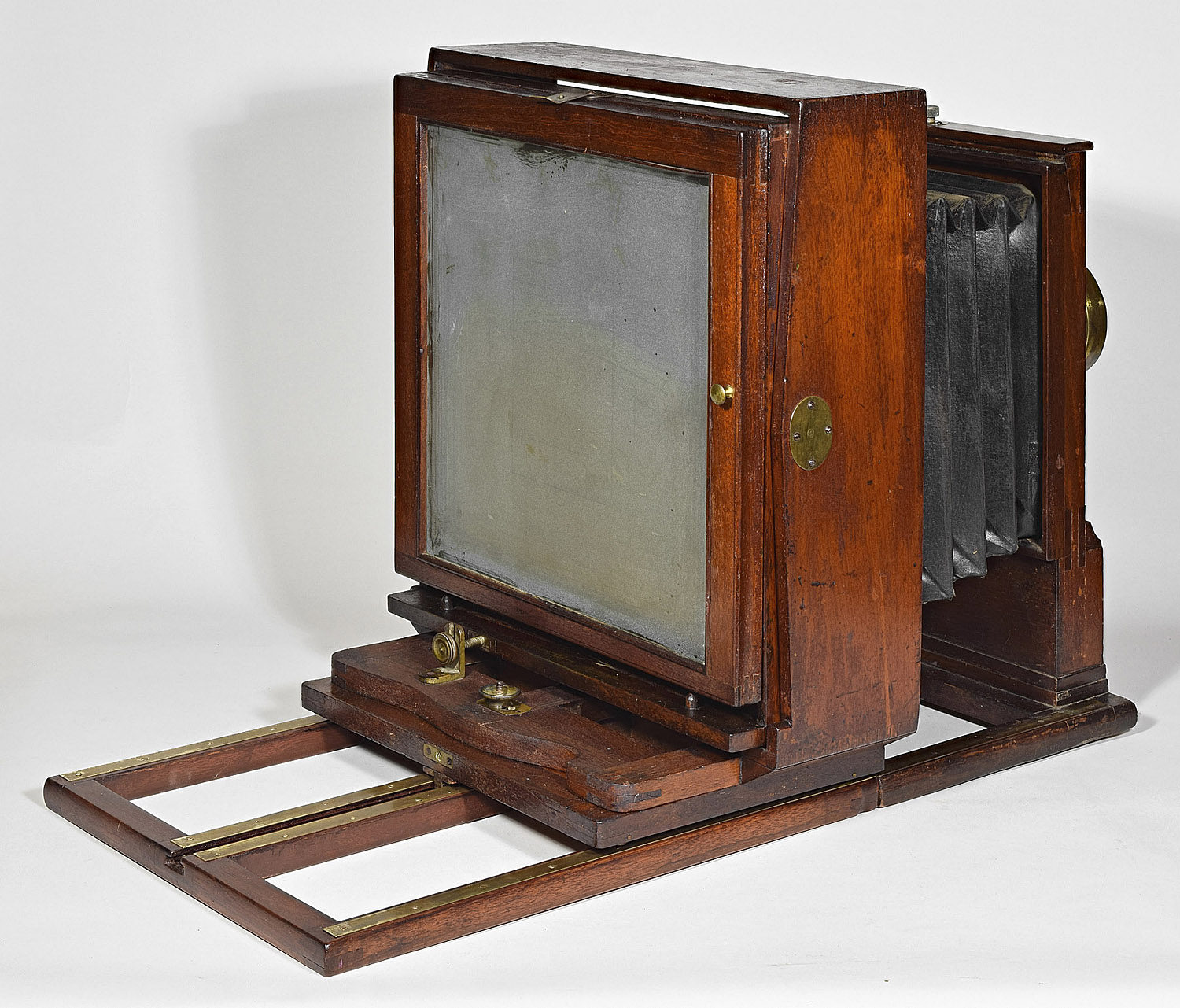
Photo 32:
Reassembled Camera, showing the new platform in use.
8. Lens Board and Lens
The lens board that came with the camera is the original Semmendinger
lens board, which has two stamps:
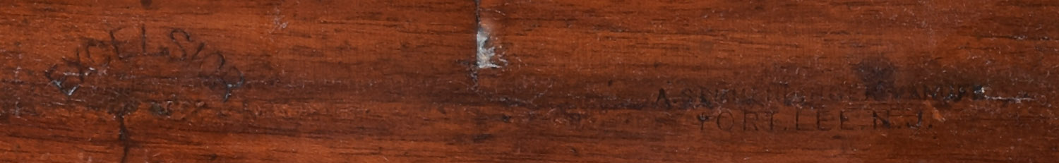
Photo 33:
Stamps on upper lens board: “Excelsior” (left) and “A.
Semmendinger, Manuf’r / Fort Lee, N.J.” (right).
After the accident, however, the original lens undoubtedly required a
rear platform to be used.
The owner at that time bought a large wide angle lens, which could focus
with the rear standard on the main platform or just behind it.
But the original hole in the board (about 4” diameter) was larger
than the flange for the new lens. The owner installed a large and thick
board on top of the original lens board, and then installed the new lens
on it.
Since the lens board was original but the additional wood was ugly, I
decided to take off the additional wood, taking the board back to what
it was before the accident, despite the large number of scars from the
addition wood and many other holes.
It would have been nice to have an 11x14” lens (14-20” focal length)
whose flange was large enough to use the 4” hole, but even my 12x15” and
two 14x17” lenses are that large.
I had to use a 16x20” Somerville rapid rectilinear, which
installed without the problem of re-cutting the hole.
The lens may not focus, even with the bellows at full extension,
but it at least gets rid of the extra wood (and metal stars).
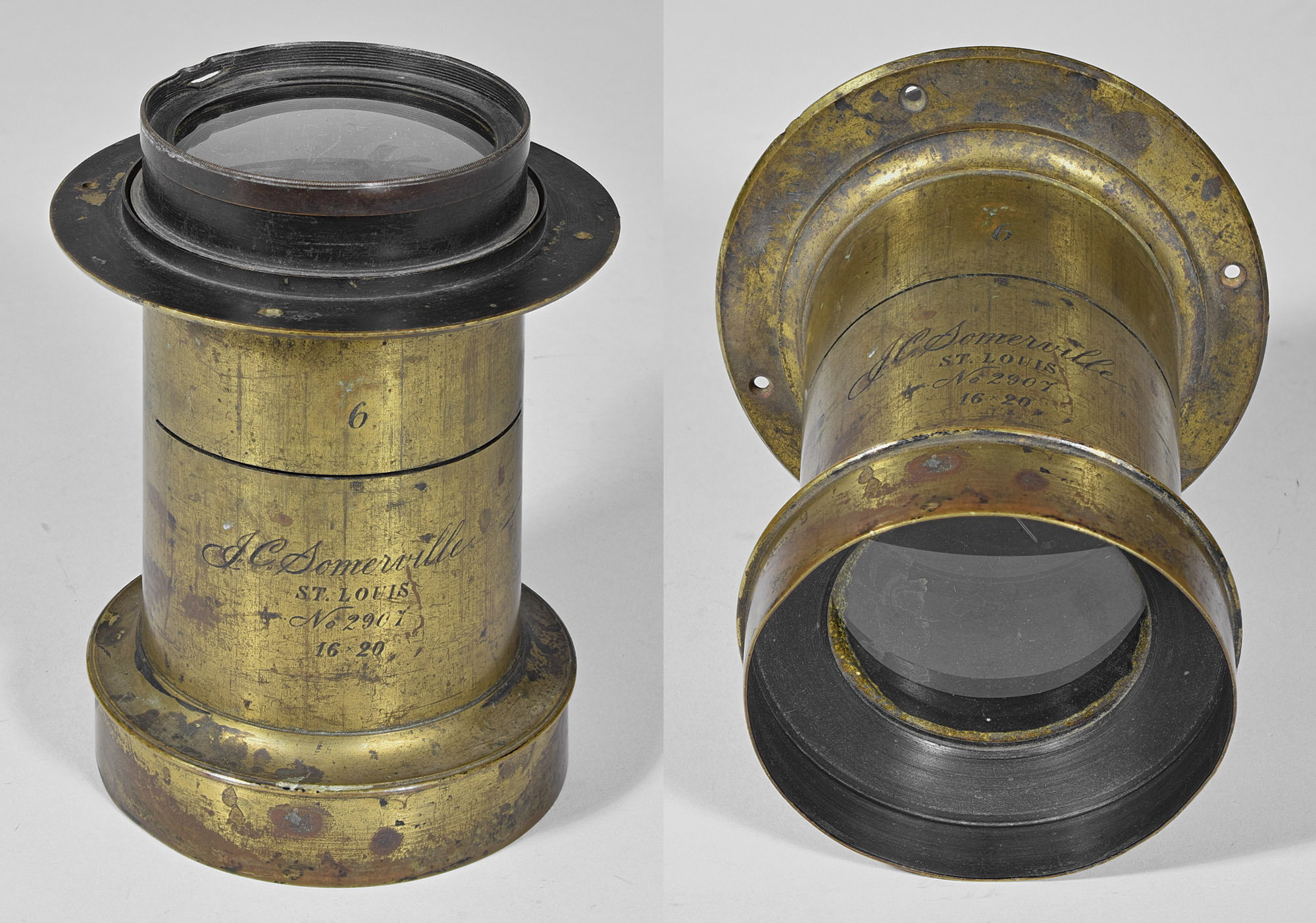
Photo 34:
Replacement 16x20” J.C. Somerville lens.
The relatively large holes left by the extra wood were filled with my
usual mahogany sawdust and hide glue wood filler.
The screw on top of the front standard that slowly moves the lens board
up or down was missing when purchased.
The replacement is a 1/4” x 20 threads per inch x 3” long solid
brass thumbscrew purchased on eBay.
The same solution of diluted brass black used for other brass
parts was used to tarnish/age it.
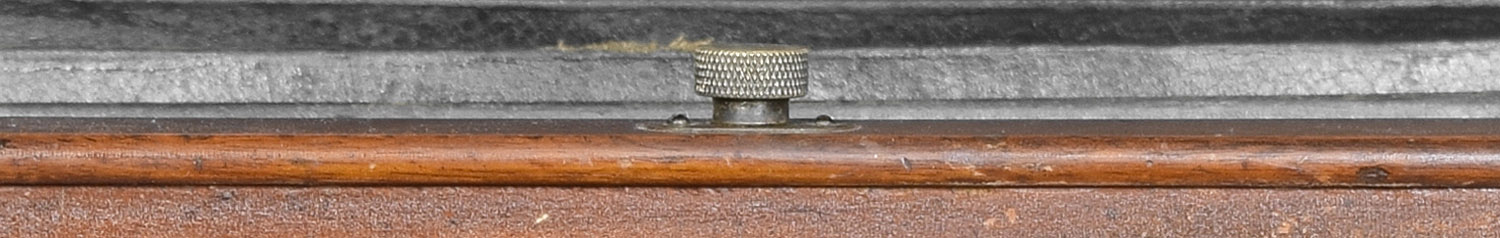
Photo 35:
Replacement Lens Board Rise Thumbscrew, Top of Front Standard.
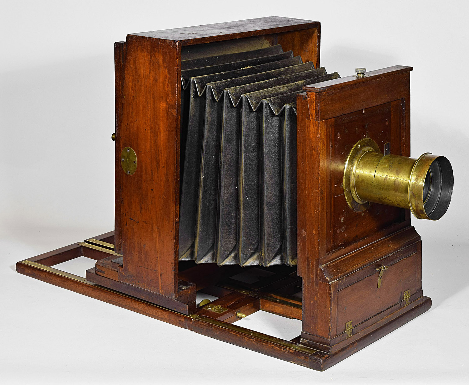
Photo 36:
Completed and Reassembled Camera from the front.
Back to Semmendinger Variation 1